
Fault Diagnosis
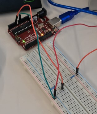
The battery levels of the camera and the motors are being read with the use of a potential divider circuit. The resistors that were utilised were selected based on the maximum battery voltage level,12 V. The data between those resistors were connected to Arduino's analog input pin and the battery levels were published to a ROS node. This circuit acts as a fault diagnosis circuit as it will inform the robot when to go to its charging location.
The initial design and testing looked as:
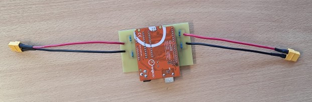
The initial design evolved into PCB design:
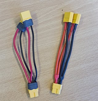
Parallel battery connectors should be utilised to connect the batteries to both the fault diagnosis PCB and their intended powering components.
The batteries have fuses, and the battery connectors are such that they cannot be connected inappropriately. These parallel connectors are secure and easy to use. They shall be utilised by the maintenance team when hot-swapping the batteries. :
More information regarding the Fault Diagnosis can be found on, Fault Diagnosis repository.